The wave propagation in porous materials, such as fibres, foams or perforates is an important topic of vibroacoustics. Porous materials are the main key to noise and vibration control. If we have to create and design absorptive surfaces of sound barriers for acoustic isolation, there are porous materials involved.
Consequently, an efficient and target oriented design process requires the understanding of wave propagation in porous materials. Especially in statistical energy analysis (SEA) software the modelling of noise control treatment consisting of porous layers and heavy layers are a key tool for such a design process.
Brief overview over the zoo of porous material parameters
The theory and application of porous material is well presented in the must-have book of from J.-F. Allard and N. Attala: Propagation of Sound in Porous Media: Modelling Sound Absorbing Materials. This reference book goes into the details of the acoustics of porous material.
As the theory is complex and detailed only relatively simple material models that can be described by fluid degrees of freedom pressure and velocity are presented in chapter 9: Deterministic Applications. However, in pyva all typical material models are implemented to model fibers, foams, fluids and elastic solids by using the transfer matrix method. In order to provide a rough estimate what the physical meaning behind those parameters is.
The parameter sets fall into three categories:
- Fluid parameters – usually air properties such as sound speed or density. The gas properties of the air determines the motion through the pores, even if it is just air
- Flow parameters – geometry parameters of the absorber micro geometry that determine the fluid flow through the pores.
- Solid parameters – The absorber frame is a solid (foam) or a fibre framework that is determined for example by isotropic material parameters as Young-modulus, Poisson coefficient and density.
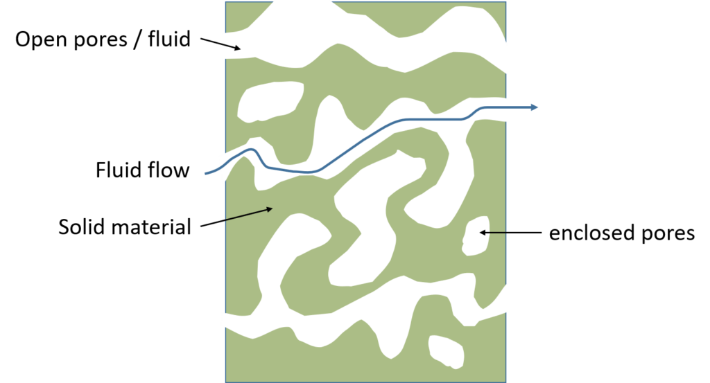
Volume Porosity
The effective volume porosity  of the absorber is the ratio of the volume part of open pores
  to the total volume
  .
.
\Phi = \frac{V_{air}}{V_t}The porosity determines the ratio of fluid and absorber frame wave motion. Absorber of very high porosity  have fluid like behavior. When the value is very low
  the porous absorber wave dynamics is similar to solid dynamics.
Tortuosity
Tortuosity  is a measure for the “sinuosity” of the fluid on the path through the absorber. The detour determines the efficient density of the absorber, because the indirect paths leads to a leverage of the mass of the fluid.
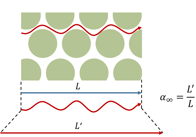
When the fluid goes through the absorber with few obstacles  . Typical values are from
  .
.
Flow resistivity
The flow resistivity  determines the pressure difference
  that occurs per unit length when fluid passes the absorber with velocity
  . This is the most important parameter regarding the damping phenomena in the absorber.
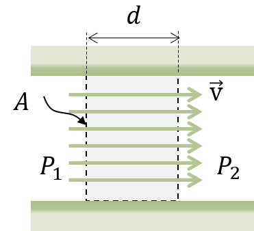
For a specimen of thickness  the flow resistivity is calculated by:
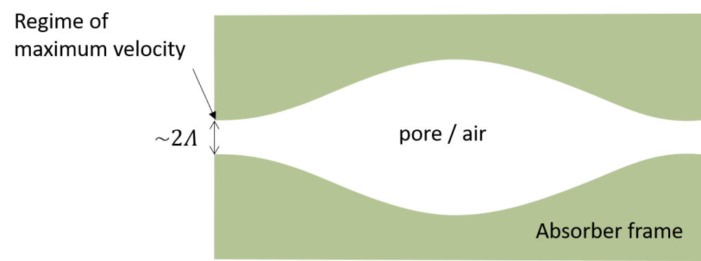
\sigma = -\frac{\Delta P}{d\,\rm{v}}Viscous characteristic length
A much more obscure parameter is the viscous characteristic length  . It influences the viscous losses of the fluid in the pores. Oddly enough it is defined without any viscous properties of the fluid but only by pore dimension and topology.
When we assume an in-viscid fluid flow through a pore with volume  and surface
  the thermal characteristic length read as:
\Lambda = 2\frac{\int_V\rm{v}^2dV}{\int_S\rm{v}^2dS}The physical meaning for this parameter can be expressed as the radius of the smallest pore in the absorber. It becomes important for higher frequencies.
Due to the microscopic structure of porous materials typical values of the viscous characteristic length are  .
.
Thermal characteristic length
Similar obscurity is valid for the next parameter – the thermal characteristic length  This time no fluid at all is used for the definition.
\Lambda' = 2\frac{\int_V dV}{\int_SdS}This parameter can be interpreted as the largest radius of the pore. This parameter is also important in the high frequency range.
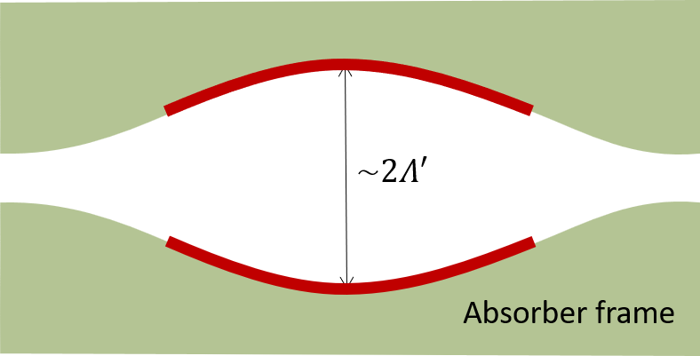
The thermal characteristic length ranges also in the micro meter, but is always larger than the viscous characteristic length, thus  .
.
Absorber frame parameters
There is not so much to say for those parameters, because they are similar to the well known isotropic elastic solid parameters. However, it is worth mentioning that all parameters are given for a vacuum. It is assumed that there is no fluid. This is also true for tests that should be performed under vacuum conditions.
Nomenclature for the book: Propagation of Sound in Porous Media
The theory of porous absorbers has one tremendous drawback: It combines fluid dynamic, thermodynamics and elastodynamics. Each discipline has its specific symbols – thus it is nearly impossible for an author in this field to used consistent and not doubled symbols.
Allard and Attala have solved this issue in a surprising way: They completely disclaimed a symbol list or nomenclature. When I have to look up formulas and models during my industrial work I use specific formulas from scratch and feel completely lost due to the vast amount of symbols. Thus, I started to create my private nomenclature to facilitate the work with this book.
I guess this might also be useful for others and therefore publish it now here in the news section. However, please note that the convention differs in many cases from mine.
Latin Symbols
| Symbol | Name | Unit | Comment |
 | pore surface | m | |
 | Prandtl number |  | |
 | speed of sound | m/s | when with index |
 | constant | not speed of sound | |
 | specific heat capacity at constant pressure | J/(kg/K) | |
 | specific heat capacity at constant volume | J/(kg K) | |
 | strain tensor | ||
 | Young modulus | Pa | |
 | kinetic energy density | J/m | |
 | shear modulus | PA | |
 | G-function for capillaries tubes | Determines the dynamic density | |
 | G-function for slits | ||
 | G-function for Johnson model | ||
 | thickness | m | |
 | wavenumber (longitudinal) | m | |
 | wavenumber (shear) | m | |
 | bulk modulus | Pa | |
 | bulk modulus of fluid | Pa | |
 | bulk modulus of the frame | Pa | In vacuum condition |
 | bulk modulus of frame material | Pa | |
 | longitudinal module | Pa | |
 | Constant in Biot theory | Pa | Maybe similar to Kc |
 | acoustic pressure | Pa | |
 | ambient pressure | Pa | |
 | potential coupling coefficient | Pa | |
 | viscous dynamic permeability | m | |
 | viscous dynamic permeability for  | m |  |
 | static thermal permeability | m |  |
 | reflection coefficient | Chapter 2 and 11. I would call it “factor” | |
| radius | m | |
 | Eg. (4.16), (4.25) | ? | Nameless and frequency dependent |
 | stress components of surface | Pa |  |
 | ambient temperature | K | |
 | displacement in  -direction -direction | m |  |
 | velocity in -direction | m/s | |
| volume | m | |
 | air volume in the absorber | m | |
 | frame volume of absorber | m | |
 | total absorber volume | m | |
 | surface impedance | Pa s/m | |
 | characteristic impedance of the fluid | Pa s/m |
Lower Case Greek Symbols
| Symbol | Name | Unit | Comment |
|---|---|---|---|
 | absorption coefficient | ||
| tortuosity | ||
 | specific heat ratio |  | |
 | coupling term |  Eq. (6.A.19) Eq. (6.A.19) | |
 | longitudinal wavenumber in solid material | 1/m | chapter 11 |
 | shear wavenumber in solid material | 1/m | chapter 11 |
 | dynamic viscosity | Pa s | |
 | dilatation | ||
 | thermal conductivity | W / (m K) | |
 | Lamé coefficients | Pa | |
 | Poisson coefficient | in elastic equations | |
| kinematic viscosity | m2/s | in fluid equations |
 | m2/s |  | |
 | acoustic density | kg/m3 | difference to ambient density |
 | density | kg/m3 | |
 | density of air | kg/m3 | |
 | density of the frame | kg/m3 | not frame material |
 | density of the frame | kg/m3 | In the coupled, porous material and in-viscous fluid |
 | density of coupling | kg/m3 |  |
 | density of the fluid | kg/m3 | In the coupled, porous material and in-viscous fluid |
 | density of the frame | kg/m3 |  |
 | density of the fluid | kg/m3 |  |
 | density of the fluid | kg/m3 | |
 | inertial coupling term | kg/m3 |  |
 | density of frame (in vacuum) | kg/m3 | |
 | density of frame material | kg/m3 | |
 | fluid density | kg/m3 | |
 | total density | kg/m3 |  (without enclosed fluid cells) |
| flow resistivity | Pa s/m4 | |
 | components of stress tensor | Pa | |
 | acoustic temperature | K | difference to ambient temperature |
Upper Case Greek Symbols
| Symbol | Name | Unit | Comment |
|---|---|---|---|
| viscous characteristic length | m | often in  m m |
| thermal characteristic length | m | often in m |
| porosity |
Indexes
| Symbol | Name | Comment |
|---|---|---|
 | prime | Denotes “thermal” (instead of viscous) but sometime also “shear” |
 | air | In material constants |
 | tilde | Denotes properties with viscous fluid, therefore also complex quantities |