This errata page is a collection of all bugs and mistakes that I noticed for the first edition. If you would like to propose some corrections please send a note to author@alexanderpeiffer.de.
A special thank you goes to Valentin who found all the bugs in chapter 7 and the legend bug in figure 8.38.
Chapter 1
Page 9 – Equation (1.37) – In the paragraph before I say signal ![]() , thus the equations should be with
, thus the equations should be with ![]()
Page 13 – Equation above equation (1.56) – the first integral should read
\Delta E_{\rm cylcle} = \int_0^Tc_v\ddot{u}\,dt=\ldots Page 15 – Figure 1.11 – left spring should have stiffness ![]()
Page 16 – Line below Equation (1.77) – The second frequency should read ![]()
Page 31 – Equation (1.147) – The last fraction should read ![]()
Page 33
Equation (1.162) – It should be ![]()
The last equation must be similar to equation (1.164), thus ![]() should be in boldsymbol
should be in boldsymbol
Page 34 – Equation (1.167), ![]() should also be in boldsymbol
should also be in boldsymbol
Page 35
Equation (1.173) – The left term should be ![]() instead of
instead of ![]()
Equation (1.177) – The left term should be ![]() instead of
instead of ![]()
Page 38 – Figure 1.24 – To be consistent with the text it should be ![]() and
and ![]()
Chapter 2
Page 44 – Last enumeration – Item 3 should be “The momentum flow out of the volume”
Page 47 – Equation (2.25) – The velocity potential should be ![]()
Page 48 – Equation (2.29) – and consequently … ![]()
Page 53
Table 2.2 – The acoustic velocity formula should read ![]()
Equation (2.59) – The last expression should be ![]()
Page 54
Equation (2.65) – It should read ![]()
The equation reference (2.30) is not correct it should be (2.65)
Page 55
Equation (2.68) – ![]()
Equation (2.69) – ![]()
Page 57
Equation (2.85) – It should by ![]() instead of
instead of ![]()
Equation (2.86) – The time average must be used ![]() instead of
instead of ![]()
Page 58 – Equations (2.87) and (2.88) – Same correction as for equation (2.86)
Page 59 – Equations (2.97) – (2.100) – All ![]() and
and ![]() must be replaced by
must be replaced by ![]() and
and ![]()
Page 60
Equations (2.101) – (2.104) – All ![]() ,
,![]() ,
,![]() and
and ![]() must be replaced by
must be replaced by ![]() ,
,![]() ,
,![]() and
and ![]()
Equation (2.101) – In the first line is should read ![]()
Page 62 – Equations (2.116) and (2.117) – The impedance symbols should be boldmath ![]()
Page 58 – Equation (2.98) – This should read ![]()
Page 70 – Above equation (2.155) – It should read ![]() .
.
Chapter 3
Page 76- Equation (3.3) – ![]()
Page 80 – Equation (3.22) – ![]()
Page 84 – Equation (3.39) – First line should read ![]()
Page 87
Reference above Equation (3.72) – It should be … Equation (3.62) leads to
Equation (3.72) – ![]()
Page 111 – Paragraph below (3.21b) – Insert as first sentence: Considering ![]() as the real and positive solution, hence
as the real and positive solution, hence ![]() .
.
Page 113 – Equations (3.222)-(3.224) – Replace ![]() by
by ![]()
Page 114 – Equation (3.225) – Replace ![]() by
by ![]()
Page 115
Equation (3.230) – The second term should read ![]()
Equation (3.231) – In the nominator it should read ![]()
Chapter 4
Page 120 Figure 4.1 – The radius is ![]() and not
and not ![]()
Page 135
Figure 4.12 – Missing unit at y-axis label. Use ![]()
Equation (4.76) – It would be more consistent to use ![]() as index in the sum
as index in the sum
\bm{p}(\vec{r}) = \sum_{m=0}^\infty \bm{p}'_m \Phi_m(\bf{r})Equation (4.77) – The first integral should read as follows
\int_{V} \sum_m^\infty\bm{p}_m'\Phi_m(\bf{r}) (\bm{k}^2 - k_n^2) \Phi_n(\bf{r}) dVEquation (4.78) – There must be a ![]() in the sum over
in the sum over ![]() .
.
Page 136 Equation (4.84) – Remove conjugate star, not required for real modes
Page 137
Paragraph below Equation (4.86) – it should read ![]()
Equation (4.87) – Third term must be ![]()
Page 141 Last paragraph – first element and not fist element
Page 141 Equation (4.103) – For better consistence with Figure 4.16 ![]() would be better
would be better
Chapter 5
Page 151 Section 5.3.1 – First sentence – it should be in-homogenous form.
Chapter 6
Page 161 Equation (6.3) – The square should be removed and it should read ![]()
Page 163 Equation (6.12) – The cosine argument must be corrected to ![]()
Page 166
In the first line the formula should read ![]()
Equation 6.21 – The ![]() in the first line should be removed
in the first line should be removed
Page 169
Equations (6.33)-(6.35) – The ![]() factor is missing for all sums.
factor is missing for all sums.
Equations (6.34)-(6.35) – The last ![]() should read
should read ![]()
Page 170
Equations (6.37) – Remove the hat from all pressure symbols ![]() is correct
is correct
Equations (6.38) – Replace ![]() by
by ![]()
Page 175/176 Figure 6.9 and 6.10 – Right hand side. Label of y-axis: ![]() should not be boldsymbol
should not be boldsymbol
Page 180
Equation (6.63) – The nominator should read ![]()
Equation in section 6.4.1.4 – ![]() should not be boldsymbol. However, for figures 6.17 and 6.18 I used equation (3.225)
should not be boldsymbol. However, for figures 6.17 and 6.18 I used equation (3.225)
Section 6.4.2 – It is worth mentioning that the plate is made of aluminum
Figure 6.14 – The density variation in the caption should be 2% not 1%
Page 188
Equation (6.76) – Both upper integral limits must be ![]()
Equation (6.78) – The energy ![]() is missing in the right term
is missing in the right term
Page 192 – Equation below (6.92) – Second sine should include a ![]() and not an
and not an ![]()
Chapter 7
Page 207 Equation (7.18) – The last radiation stiffness should be ![]() instead of
instead of ![]()
Page 208
Section 7.3.1 heading – Exchange m and n
Globally it would be better to stay with the original heading and exchange ![]() and
and ![]() in the text and all formulas, because his would correspond better to figure 7.5
in the text and all formulas, because his would correspond better to figure 7.5
Equation (7.22) – The index ![]() is missing, it should be
is missing, it should be ![]()
Page 210 Equations (7.28) and (7.30) – The index ![]() should be used consequently in all formulas as sum index
should be used consequently in all formulas as sum index
Page 211 Equation (7.32) – The factor ![]() is missing after both large parenthesis
is missing after both large parenthesis
Page 215
Equation (7.40) – ![]() instead of
instead of ![]()
Last line of last paragraph – response instead of reponse
Page 218 Figure 7.13 – The SEA-Matrix must read ![]() instead of
instead of ![]()
Page 220 Equation (7.47) – The modal coordinate ![]() is missing
is missing
Chapter 8
Page 226 Last paragraph – … is modified by an ![]() factor instead of
factor instead of ![]()
Page 227 First sentence – ![]() must be replaced by
must be replaced by ![]()
Page 231 Figure 8.5 – Label of y-axis: TL/dB instead of TL in dB Page
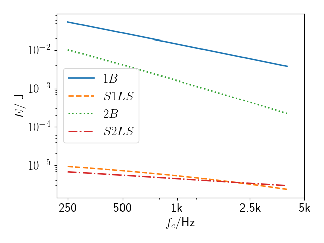
Page 233 Figure 8.8 – Due to a bug in the code spring curves are wrong. See new figure.
Page 234 Figure 8.10 – Label of y-axis: TL/dB instead of TL in dB
Page 238 This item in description – ![]() instead of
instead of ![]()
Page 242 Equation (8.74) – The equal sign before the ![]() must be removed
must be removed
Page 239 Equation (8.51) – in the first row the integral is missing, The second integral runs over ![]()
\Pi = \frac{1}{2} \int_S Re\{ {\bm v}_z^*(x,y){\bm p}(x,y) \} dS Page 240 Equation (8.59) – last sine should read ![]()
Page 245 Equation (8.73) – The stiffness is complex, thus ![]()
Page 247 Equation (8.94) – The stiffness is complex, thus and there is an ![]() missing in the last term
missing in the last term
\bm{D}_{\rm tot}''(k_a,\vartheta)=m''\omega^2\left[\frac{ k_a^4\sin^4\vartheta}{k_B^4} -1 \right]
			- j\omega\frac{2 \rho_0c_0}{\cos\vartheta}
Page 250
Equation (8.101) – it should read ![]()
Equation (8.103) – remove useless ![]() in the middle
in the middle
Page 251 Equation (8.105) – use ![]() and
and ![]()
Page 253 After Equations (8.108a-d) – it should read ![]()
Page 255 Coordinate vector after Equation (8.118) – use bold ![]()
Page 256
Equation (8.21) – the displacement vector is missing after the first matrix
Equation (8.23) – the amplitude vector is missing after the second matrix
Equation (8.24) – the displacement vector is missing after the first matrix and ![]()
Page 257 Paragraph below Equation (8.127) – it should be ![]() instead of
instead of ![]()
Page 258 Equation (8.131) – is should read ![]()
Page 261
Equation (8.143) – wrong index index in excitation cspd. It should be ![]()
Equation (8.147) – wrong index index in center matrix cspd. It should be ![]() and the third matrix is the hermitian of the inverse
and the third matrix is the hermitian of the inverse ![]()
Page 263
Figure 8.30 – wavenumber vector labels ![]() and
and ![]() must be exchanged
must be exchanged
Equation (8.151) – is should read ![]()
Page 267 Figure 8.38 – The legends must be exchanged. The blue line belongs to ![]()
Chapter 9
Page 287
Equation (9.76) – Should be ![]()
Paragraph before Equation (9.78) – Should be small ![]()
Page 297 – Equation (9.101) – It should read ![]()
Page 299
Equation (9.107d) – Division by porosity is missing. Use ![]() in nominator
in nominator
Equation (9.107e) – Variables should be in boldsymbol. Use ![]()
Equation (9.107f) – Variables should be in boldsymbol. Use ![]()
Equation (9.107g) – Variables should be in boldsymbol. Use ![]()
Page 301
Equation (9.109) – The last term of the denominator should read ![]()
Equation (9.110) –
{\bm R}(\vartheta)=\frac{{\bm z}(\vartheta)-\frac{{\bm z}_s(\vartheta)}{\cos(\vartheta)}}{{\bm z}(\vartheta)+\frac{{\bm z}_s(\vartheta)}{\cos(\vartheta)}}Page 302
Paragraph below Equation (6.72) – z = ρ0c0
Next paragraph – z = az0
Page 309 Figure 9.40 – Label of y-axis: First ‘perf’ index should be in roman
Page 313 Figure 9.44 – Figure caption has an index error. It should read ![]()
Page 314 Figure 9.45 – Figure caption has an index error. It should read ![]()
Page 315 Equation (9.127) – It should read as follows:
m''_{red} = \frac{m_1'' m_2''}{m_1''+m_2''}
Page 316 Figure 9.47 – Wrong figure. Should be as follows:

Chapter 10
Section 10.2.1
I really apologize for all the bugs in this section. This is an excellent example that some mistakes of a derivation are not found, because the final result was know before. In fact all equations of this section are wrong, except the final result!
Page 321
In equation (10.3) the diagonal must be corrected
\omega\begin{bmatrix}
n_1(\eta_{11} + \eta_{12}) & -n_2 \eta_{21}\\
-n_1 \eta_{12} & n_2 (\eta_{22} + \eta_{21})
\end{bmatrix}
\begin{Bmatrix}
E_1/n_1(\omega) \\ E_2/n_2(\omega)
\end{Bmatrix} = \begin{Bmatrix} \Pi_1 \\ \Pi_2 \end{Bmatrix}
Page 322
This has consequences on equation (10.4)
\begin{Bmatrix} E_1/n_1 \\ E_2/n_2 \end{Bmatrix}
= -\frac{1}{\omega^2( \eta^2_{12} n_1 - n_2 (\eta_{11}+\eta_{12})(\eta_{22}+\eta_{21})) }
\begin{bmatrix}
\frac{n_2}{n_1}\eta_{22} + \eta_{12} & \eta_{12}\\
			\eta_{12} & \eta_{11} + \eta_{12}
\end{bmatrix}
\begin{Bmatrix} \Pi_1 \\ \Pi_2 \end{Bmatrix}
and on (10.5)
E_1 = - \frac{n_1\eta_{12} +n_2\eta_{22}}{\omega^2(n_1\eta^2_{12} - n_2(\eta_{11}+\eta_{12})(\eta_{22}+\eta_{21})}\Pi_1 and (10.6)
E_2 = - \frac{n_2\eta_{12} }{\omega^2(n_1\eta^2_{12} - n_2 (\eta_{11}+\eta_{12})(\eta_{22}+\eta_{21})}\Pi_1Not to speak about (10.7) and (10.8)
p_{1,\rm rms} = -\frac{\rho_0}{2\pi^2c_0 n_1}
		\frac{n_1\eta_{12} +n_2\eta_{22}}{n_1\eta^2_{12} - n_2 (\eta_{11}+\eta_{12})(\eta_{22}+\eta_{21})}\Pi_1
p_{2,\rm rms} = -\frac{\rho_0}{2\pi^2c_0}
\frac{\eta_{12} }{n_1\eta^2_{12} - n_2 (\eta_{11}+\eta_{12})(\eta_{22}+\eta_{21})}\Pi_1The pressure ratio (10.9) also has totally different look
\frac{p^2_{2,\rm rms}}{p^2_{1,\rm rms}} = \frac{n_1(\omega)\eta_{12}}{n_1(\omega)\eta_{12}+n_2(\omega)\eta_{22})}Leaving different result for the coupling loss factor in equation (10.10). Note the involved ratio of modal densities.
\eta_{12} = \frac{p^2_{2,\rm rms}}{p^2_{1,\rm rms}}\frac{n_2(\omega)}{n_1(\omega)\left(1-\frac{p^2_{2,\rm rms}}{p^2_{1,\rm rms}}\right)} \approx \eta_{22}\frac{p^2_{2,\rm rms}}{p^2_{1,\rm rms}}\frac{n_2(\omega)}{n_1(\omega)}To be precise, the volume in equation (10.11) is ![]()
\eta_{22} = \frac{A_s c_0}{4 V_2 \omega}Page 323
The volume in the ![]() –
–![]() relationship must be
relationship must be ![]() and this – in combination with the modal density ratios – gives the final result in equation (10.12).
and this – in combination with the modal density ratios – gives the final result in equation (10.12).
\left<\tau_{12}\right>  = \frac{4 V_1 \omega}{c_0 S_j} \eta_{12} = \frac{p^2_{2,\rm rms}}{p^2_{1,\rm rms}}\frac{V_1 n_2(\omega)}{V_2 n_1(\omega)} \frac{A_s}{S_j}
                            = \frac{p^2_{2,\rm rms}}{p^2_{1,\rm rms}}\frac{A_s}{S_j}
Page 325 Figure 10.4 – Label at y-axis should be ![]()
Page 327
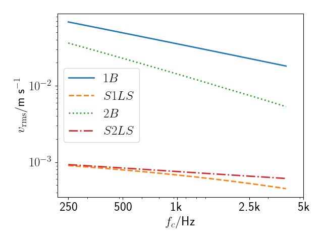
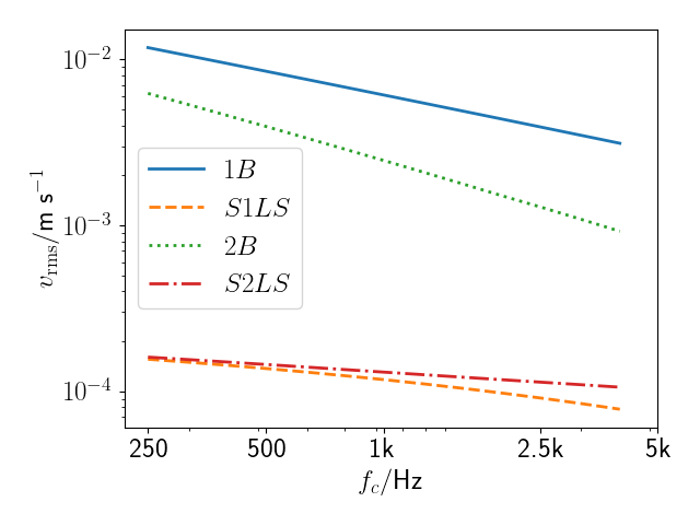
Figure 10.7 and 10.8 are not correct due to a bug in the pyva software


Page 328 Figure 10.9 is not correct due to a bug in the pyva software

Chapter 12
Page 361 Figure 12.1 – The Helmholtz number should be ![]()
Page 372 – Section 12.3 Last sentence of first paragraph – prototype instead of pototype.
Appendix A
Page 424 Equations (A.68),(A.70)-(A.73) – The force symbol should be in capital letters ![]()
Appendix B
Page 426 Equation (B.17) – The upper index should read ![]()
Page 429 Figure B.2 – wavenumber vector labels ![]() and
and ![]() must be exchanged
must be exchanged
Page 435 Paragraph below equation (B.73) – it should read “only ![]() remains real …”
remains real …”
Page 436 Equations (B.79-80) – The upper right coefficient in the matrix requires a second right parenthesis
Index
Page 445 coupling loss factor, non-resonant and resonant instead of resonsant
